The equalizers have delay $D$ and transfer function $F(z)$. Given a discrete time transfer function $H\left( z \right)$ of the channel the equalizers' transfer functions are given as:
- ZF-ideal: $F(z) = \frac{z^{-D}}{H(z)}$ Note that this equalizer can get unstable, if $H(z)$ has zeros outside the unit circle, i.e. $|z|>1$.
The output of a FIR equalizer can be represented in vector matrix notation: $$\mathbf{H\cdot f = i + \Delta i} \text{ ,}$$ where $\mathbf{H}$ denotes a convolutional matrix, vector $\mathbf{f}$ holds the equalizer coefficients, and $\mathbf{i}$ denotes the desired equalizer output, i.e. all entries are zero except the $D$-th entry which equals $1$. Moreover, $\mathbf{\Delta i}$ denotes the residual equalizer error. The goal of FIR equalizer design is to approximate $\mathbf{i}$ with $\mathbf{f}$, while keeping $\mathbf{\Delta i}$ low. We assume that the equalizer has $M+1$ cofficients and that the channel impulse response has $L+1$ coefficients. It can be shown, that the linear equation system of above is overdetermined, i.e. $\mathbf{i}$ has size $L+M+1\times 1$, whereas $\mathbf{f}$ is of size $M+1\times1$. Thus, $\mathbf{i}$ can be only approximated. The webdemo considers the following methods:
- ZF-trunc: Matrix $\mathbf{H}$ is truncated to $\mathbf{H}_{\text{tr}}$ such that the equation system has a unique solution. In particular, this webdemo considers the $D$-th row of $\mathbf{H}$ as well as the sourrounding rows symmetrically (if possible). The equation system $\mathbf{H}_\text{tr}\mathbf{\cdot f = i}_\text{tr}$ is solved for $\mathbf{f}$ and $\mathbf{\Delta i}$ is taken as is.
- ZF-trunc-opt: Coefficients $\mathbf{f}$ are selected such that the quadratic error of $\mathbf{\Delta i}$, i.e. $\mathbf{\Delta i}^H\cdot \mathbf{\Delta i}$ is minimized. It can be shown, that $\mathbf{f}$ is given by $\mathbf{f} = \mathbf{(H^H H)^{-1}\cdot H^H \cdot i}$
- MMSE: The MMSE works as the ZF-trunc-opt method, however, it considers additionally the noise power $\sigma^2$ of the channel. In this case, the equalizer coefficients result in $\mathbf{f} = \mathbf{(H^H H +} \sigma^2 \mathbf{I)^{-1}\cdot H^H \cdot i}$ with $\mathbf{I}$ being the identity matrix of appropriate size. The MMSE solution minimizes $\mathbf{(\Delta i + n)}^H\cdot \mathbf{(\Delta i + n)}$ with $\mathbf{n}$ holding noise samples with zero mean and variance $\sigma^2$.
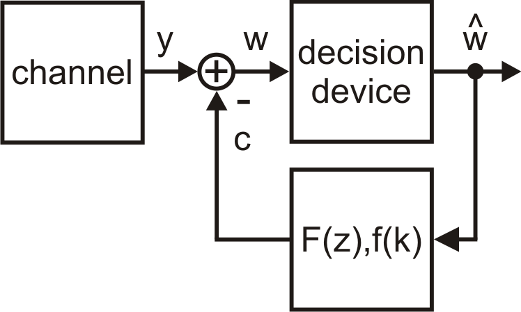
The DF equalizer incorporates the decision process at the receiver. A block diagram is given below. The correction signal $c$ is substracted from the receive signal $y$. The corrected receive signal $w=y-c$ is passed to a decision or quantization device which has output signal $\hat{w}$ given by $$\hat{w}=\begin{cases} +1 & w\geq 0 \\ -1 & w<0 \end{cases}$$ for BPSK transmission. The signal $\hat{w}$ is the input signal of a FIR filter with coefficients $f(k)$, which generates signal $c$. Its coefficients $f(k)$ are defined as $$f(k)=\begin{cases} h(k+D) & k>0 \\ 0 & \text{else} \end{cases} \text{ .}$$

Note that the DF equalizer can be affected by decision errors and that the DF equalizer can only remove successor samples (predecessors can not be suppressed), i.e. performance decreases for increasing $\sigma^2$ and $D$ in general.
