Basic terminology used in case of filters design:
- order $N$: Filter order determines the sharpness of response in passband as well it also determines number of delay elements used.
- Cutoff frequency $\Omega_{c}$: cutoff frequency represents the $-3 {\text{dB}}$ gain from maximum gain.
- passband: a frequency range for which the frequency content is allowed to pass through filter.
- stopband: a frequency range for which frequency content is not allowed through filter.
Analog filters can be designed with many approaches for example Butterworth, Chebyshev, Elliptic etc. However in this webdemo, we are considering Butterworth design itself, as it is the simplest form of prototype to design and realization for the digital equivalent of same. In addition, it gives maximal flat frequency response in passband [1] [2] . The transfer function of analog filter $H_{a}(s)$ is expressed as:
-
$$H_{a}(s)=\frac{B_{a}(s)}{A_{a}(s)}$$
where
- Laplace transform of numerator polynomial (zeros of the transfer function): $B_{a}(s)$
- Laplace transform of denominator polynomial (poles of the transfer function): $A_{a}(s)$ [2]
Low pass Butterworth filter design
The prototype for analog filters design is low-pass filter, after evaluating poles and zeros of low pass filters, it gives a simple way to transform poles and zeros of low pass filter to corresponding high pass and band pass filters poles and zeros.
The simplest approach to design analog filters is to have prototype of low-pass filters. After evaluating poles and zeros of low pass filters, it gives a simple mathematical way to transform them to corresponding high pass and band pass filters poles and zeros. Like all filters, the typical prototype is the low-pass filter, from which the poles and zeros of low pass filter are transformed to high pass filter poles and zeros or band pass filters poles and zeros.
For Butterworth filter with transfer function $H(s)$ and $N-th$ order the corresponding gain $G(\Omega)$ is given as
$$ G^2(\Omega)=|H(j\Omega)|^2= \frac{1}{1+\left(\frac{\Omega}{\Omega_{c}}\right)^{2N}} .$$
It is seen that with the increase in the order of the filter ($N$) , frequency response gets sharper and gain becomes maximal flat. The poles lies equidistance on the circle of radius $\Omega_{c}$ and symmetric about imaginary axis. For stability of filter, it is important to have poles in the negative real half-plane of $s$ [1]
$$ G(s)=H(s)H(-s)= \frac{1}{1+\left(\frac{-s^2}{\Omega_{c}}\right)^{2N}} {.}$$
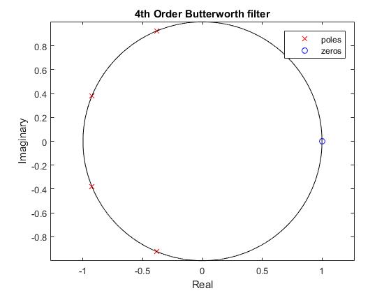
The $k-th$ pole is specified by, $$p_{k} =e^{(j*(2k+N-1)*(pi))/(2N)},$$ where $k$=1,2,3,....$N$.
The transfer function may be written in terms of these poles as, $$ H(s)=\frac{1}{\prod_{k=1}^N (s-p_{k})/ \Omega_{c}} .$$ [2]
Low pass to High pass conversion
As derived in [2] , if the poles of low pass filters have been already obtained, the poles and zeros of the corresonding high-pass filter can be obtained by transforming the low-pass filter poles according to following algorithm.
If $H_{\text{LP}}$ has a pole at $p_{k}$, $H_{\text{HP}}$ will have pole at
-
$${p_{k,\text{HP}}}=\frac{\Omega_{c,\text{HP}}}{p_{k(LP)}}$$
where,
- high pass cutoff frequency: $\Omega_{c,\text{HP}}$
- high pass filter poles: ${p_{k,HP}}$
- low pass filter poles: ${p_{k,LP}}$. .
With this new poles for high pass filter we can obtain frequency response for corresponding high pass filter i.e ${H_\text{HP}}(s).$
Low pass to Band pass conversion
As per the algorithm of filter conversion band pass filter is obtained from low pass filter by given approach. [2] It is observed that low pass filter pole at $p_{k}$, maps onto two poles of band pass filter. And numerator of band pass filter function is adjusted such that filter gain at $s=j\Omega_0$ is equal to unity.
We let,
$$p_{k}=\frac{s^2+\Omega_{0}^2}{Bs}, $$ which can be further simplified as, $$ s^2-p_{k}Bs+\Omega_{0}^2=0$$
where $B$ denotes the bandwidth and $\Omega_{0}$ denotes the centre frequency of the band pass filters being implemented.
Solution of equation gives two poles in band pass filter function with repect to requirement for given low pass pole $p_{k}$. For example if low pass filter has order 3 then, the band pass filter obtained from it will have 6 poles (twice the order of low pass filter) . [2]