Polyphase structure is useful for building filter banks as well as for multirate applications in digital signal processing.
The digital finite impulse response (FIR) filter can be derived as :
$$ H(z) = \sum\limits_{n = 0}^{N-1} {B_k(z^N)z^{ - k} } $$The polynomial $B_k(z^N)$ are the $z$ transform of the sequence $b_k[n]$ $$b_k[n]=h[nN+k], 0\le k\le N-1. $$
This means that, we have grouped the impulse response $h[n]$ into $N$ subsequences $b_k[n]$.The $k$-th subsequence $b_k[n]$ is obtained from the original impulse response $h[n]$ by starting at $h[n+k]$ and then by downsampling the factor $N$. [3] Outcome : As derived in [3], the polyphase structure of filter carried out by feeding the odd and even samples from sequence in parallel to the filter , which results efficient halving the opeating frequency. the odd and even samples from a sequence In this webdemo the filter can be given as the two polyphase components($N$=2)
i.e $$ H(z) = \sum\limits_{k = 0}^{1} {B_k(z^N)z^{-k} } $$For example, the FIR filter is expressed as:
$$ H(z) = 1+5 z^{-1}+7 z^{-2}+9 z^{-3} $$ [3]then it is expressed as two polyphase components as,
$$ H(z) =z^{-0}(1+7 z^{-2})+z^{-1}(5+9 z^{-2})=B_0(z^{2})+z^{-1} B_1(z^{2}). $$Halfband Filter
A digital half-band filter is nothing but low pass finite impulse response (FIR) filter which takes only half samples as that of original samples for competence and whose cutting edge frequencies (passband, stopband) are centered quarter to that sampling frequency $f_{s}$ . Because of this properties it's most useful in case of downsampling of digital signals with efficient manner.for half-band filters $({\Omega_n}={2{\pi}{f/fn}})$ represents the normalised frequency and $f_{n}={1/T}$ the sampling rate.
Since digital halfband filter are more efficient they are used as basic building block for digital signal processing applications. They are, for instance in this webdemo used in decimators for sample rate alteration by a factor of two. [4][5][6]
Mathematical analysis of polyphase digital IIR filter structure
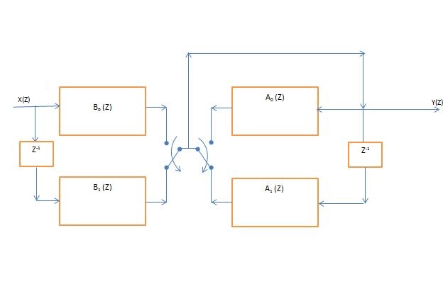
- By using above concepts of polyphase implementations and half band filter, in this webdemo we have formed IIR Polyphase ($N$=2) by consedering two polynomials of transfer function ( numerator $B(z)$ and denominator $A(z)$ ) of digital filter obatained through bilinear trasformation as mentioned in last side as follows: $$ H(z) = \frac{\sum\limits_{k = 0}^{1} {B_k(z^N)z^{-k} }}{\sum\limits_{k = 0}^{1} {A_k(z^N)z^{-k} } }=\frac{B(z)}{A(z)}. $$
- So numerator polynomial is divided in two subfilters as denominator in two subfilters. These all filters are lowpass FIR filters.
- The transfer functions of both subfilters are added for denominator and numerator separately taking into account the delay element ( multiplication of $z^{-1}$ ). After this, numerator and denominator are combined by dividing their transfer function elementwise.
- By dividing numerator FIR filter reponse by denominator response gives the same response of IIR digital response as that of the digital IIR filter obatined by bilinear transformation from analog IIR filter.The result is observed in webdemo in dropdown list option "Digital Polyphase"[4][5][6][7][8]