Applying a finite impulse response (FIR) filter with impulse response $h_{n}=h[n]$ is a commonly used technique to shape the spectrum of a signal [7], [8]. The output signal $y_{n}=y[n]$ is determined by the discrete convolution $*$ of the impulse response with the input signal $x_{n}=x[n]$
$$
y[n]=(h\ast x)[n]=\sum_{i=-\infty}^{\infty}h[i]\cdot x[n-i]
$$
This sum can be simplified for causal FIR filters of length $L$
$$
y[n]=\sum_{i=0}^{L-1}h[i]\cdot x[n-i]
$$
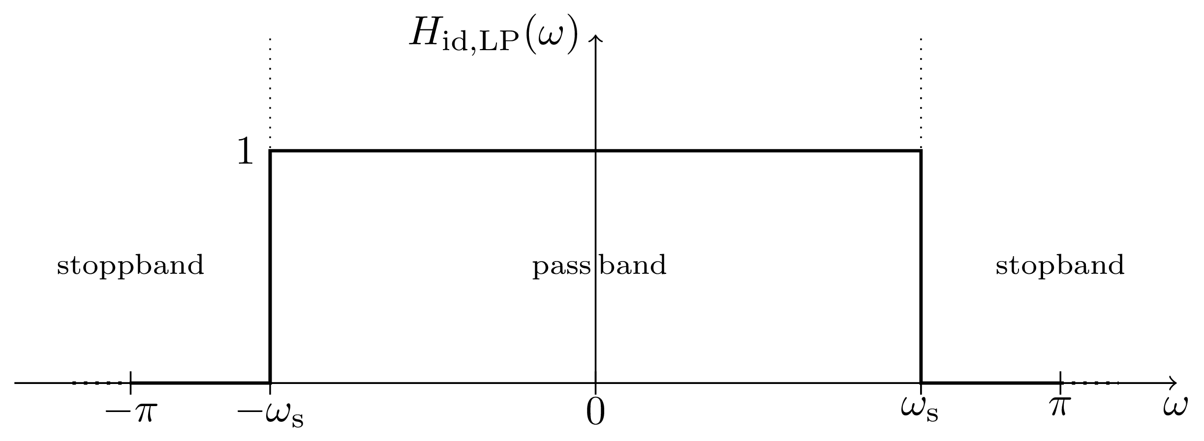
In order to construct complex valued notch filters we first design lowpass filters with a desired frequency response $H_{\mathrm{id,LP}}(\omega)$ which are then shifted by $\omega_{\mathrm{off}}$ to the desired frequency range
$$
H_{\mathrm{id,LP}}(\omega)=\begin{cases}
1 & |\omega|<\omega_{\mathrm{s}}\\
0 & \omega_{\mathrm{s}}<|\omega|\leq\pi
\end{cases}
$$
The cutoff frequency $\omega_{\mathrm{s}}$ is chosen in a way so that the resulting normalized notch width $w$ is as wide as the to supressed area from $n_{\mathrm{F}}$ to $n_{\mathrm{L}}$
$$
\frac{2\pi}{N_{\mathrm{sub}}}\cdot w=\frac{2\pi}{N_{\mathrm{sub}}}\cdot\left(n_{\mathrm{L}}-n_{\mathrm{F}}\right)=2\cdot(\pi-\omega_{\mathrm{s}})
$$
This results in the following equation for $\omega_{\mathrm{s}}$
$$
\omega_{\mathrm{s}}=\pi\cdot\left(1-\frac{w}{N_{\mathrm{sub}}}\right)
$$
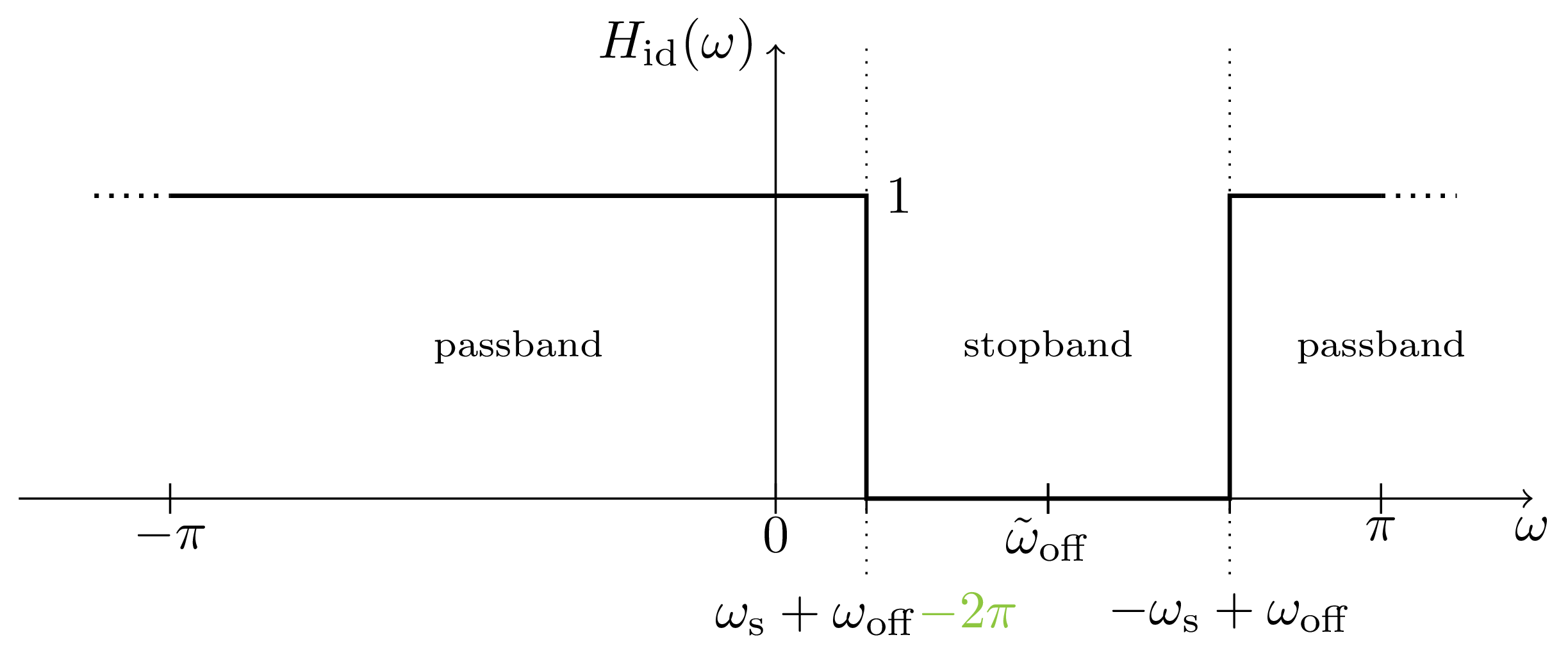
Next, we shift the frequency response by $\omega_{\mathrm{off}}$ to create the notch filter
$$
\omega_{\mathrm{off}}=\pi+\frac{n_{\mathrm{F}}+n_{\mathrm{L}}}{2}\cdot\frac{2\pi}{N_{\mathrm{sub}}}=\pi+\tilde{\omega}_{\mathrm{off}}
$$
Which results in the following frequency response
$$
H_{\mathrm{id}}(\omega)=H_{\mathrm{id,LP}}(\omega-\omega_{\mathrm{off}})
$$
This frequency shift results in a multiplication with an exponential function in time domain
$$
h_{\mathrm{id}}[n]=h_{\mathrm{id,LP}}[n]\cdot e^{\mathrm{j}\omega_{\mathrm{off}}n}
$$
The hard jump between the passband and the stopband can not be realized by a finite filter structure due to Gibbs phenomenon. Therefore we define a transition area of width $\Delta\omega$ where the filter can transition from the passband to the stopband. The width of this transition area can be defined by the number of subcarriers $b$ covered by the transition area
$$
\Delta\omega=\frac{2\pi}{N_{\mathrm{sub}}}\cdot b
$$
To fully parametrize the desired frequency response of the filter we define $\omega_{\mathrm{d}}$ to be the cutoff frequency of the passband
$$
\omega_{\mathrm{d}}=\omega_{\mathrm{s}}-\Delta\omega=\pi\cdot\left(1-\frac{w-2b}{N_{\mathrm{sub}}}\right)
$$
The resulting frequency response is parametrized as follows
$$
H_{\mathrm{id,LP}}(\omega)=\begin{cases}
1 & |\omega|\leq\omega_{\mathrm{d}}\\
don't\,care & \omega_{\mathrm{d}}<|\omega|<\omega_{\mathrm{s}}\\
0 & \omega_{\mathrm{s}}\leq|\omega|\leq\pi
\end{cases}
$$
![]()