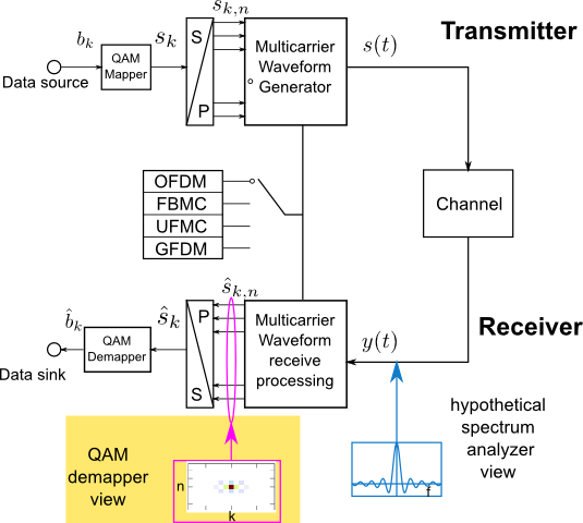
 In the previous demo, we studied the time and frequency properties of various waveform technologies from the view point of a spectrum analyzer without applying any receive processing
such as matched filtering.
From now on, receive processing for considered waveform technologies is included. The following demo shows the estimated symbols at each subcarrier $n$ and time $k$ from the view point of a QAM-demapper. For illustration purpose, only one subcarrier carries data at time $k_{0}=0$. The transmitted signal can be written as $$ s(t)= s_{k_{0},n_{0}}g(t)e^{j2\pi f_{\rm{sub}}n_{0}t}, $$ where $s_{k_{0},n_{0}}$ is in general QAM-symbols, here for simplicity BPSK is used, i.e. $s_{k,n} \in \{-1,1\}$. This signal arrives at receiver with many impairments such as carrier frequency offset (caused by Doppler-shift, frequency mismatch of oscillators) and timing offset (signal propagation time, residual synchronization error). Since future 5G is expected to support communications for both "high-end" (e.g. Tablets) and "low-end" (e.g. simple sensors) devices, robustness against time and frequency misalignment of potential 5G waveform candidate plays a major role. Thus, robustness of the aforementioned waveform candidates is investigated under carrier frequency offset $\epsilon$ and timing offset $k_{\rm{off}}$. Furthermore, the normalized carrier frequency offset $\Delta\epsilon$ is normalized by the subcarrier spacing $$ \Delta\epsilon = \frac{\epsilon}{f_{\rm{sub}}}. $$ In this webdemo, the timing offset $k_{\rm{off}}$ is restricted to sample level (integer numbers). The normalized timing offset $\Delta k$ is given by $$ \Delta k = \frac{k_{\rm{off}}}{N_{\rm{MC}}}, $$ where $N_{\rm{MC}}$ is the total number of samples per multi-carrier symbol, e.g. $N_{\rm{MC}}=N_{\rm{sub}}$ for OFDM and $N_{\rm{MC}}=L_{F}+N_{\rm{sub}}$ for UFMC. After receive processing, symbol estimates $\hat{s}_{k,n}$ are obtained. The impact of timing- and frequency offset is quantified by mean squared error $J$ and it is written as $$ J=\sum_{k}\sum_{n}|\hat{s}_{k,n}-s_{k,n}|^2. $$
Optionally, another resource element with the frequency index $k_{0}+k_{\rm{dist}}$ and time index $n_{0}+n_{\rm{dist}}$ can be made active for transmission. $k_{\rm{dist}}$ and $n_{\rm{dist}}$ is the distance to the above mentioned resource element in time and frequency, respectively. They can be specified by users. By doing so, the so called signal to interference ratio (SIR) can be computed as $$ \rm{SIR} =\frac{|s_{k_{0}+k_{\rm{dist}},n_{0}+n_{\rm{dist}}}(\Delta\epsilon,\Delta k)|^2}{|s_{k_{0},n_{0}}(\Delta\epsilon,\Delta k)|^2}. $$
At last, the receive processing of respective waveform technologies are shown here
- OFDM: perfect equalization of phase is applied.
- FBMC: zero-forcing equalization is applied.
- UFMC: perfect equalization of phase is applied.
- GFDM: matched filter receiver with perfect phase equalization.
