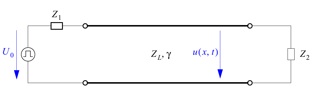
The following webdemo shows an impulse travelling on an electrical line. We assume a electrical line with a real-valued wave impedance $Z_L$, a constant attenuation coefficient $\alpha$ , and a phase coefficient $\beta$ which is linear in $\omega$. Recalling the definition of the phase velocity $v_{ph}=\frac{\omega}{\beta}$, we can rewrite $\beta = \frac{\omega}{v_{ph}}$. According to the lecture, the voltage transfer can be expressed as $$ U(x,j\omega) = U_0(j\omega) \frac{1-r_1}{2} \frac{e^{-\alpha x}e^{-j\frac{\omega}{v_ph} x}+r_2e^{-\alpha(2\ell-x)}e^{-j\frac{\omega}{v_{ph}}(2\ell-x)}}{1-r_1r_2e^{-2(\alpha+j\frac{\omega}{v_{ph}})\ell}} $$ where $r_1$ and $r_2$ denote the reflection coefficients at the beginning and at the end of the line, respectively. The reflection coefficient $r_i$ is given by $r_i = \frac{Z_i-Z_L}{Z_i+Z_L}$ with $Z_1$ and $Z_2$ being the imepdance at the input or output of the line, respectively. $\ell$ denotes the line length, $0\leq x \leq \ell$ is the coordinate of any observation point along the line.